top of page
Battery Powered LED Light PCB


Our Intro
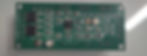
The compact LED lighting PCB uses a double-sided PCBA (Printed Circuit Board Assembly) to minimize size while supporting RGB (Red, Green, Blue) and programmable LED PCBs. Powered by a 3-cell LiPo (Lithium Polymer) battery, it features an integrated charging system compatible with USB-C, DC barrel jack, and other connectors. A built-in BMS (Battery Management System) ensures cell balancing, undervoltage, and overvoltage protection. The PCB connects to a MCU (Microcontroller Unit) for advanced lighting control and enables remote monitoring of battery status, including charge percentage.
Compact Double-Sided PCBA – Minimizes size while maintaining high functionality.
Supports RGB & Programmable LED PCBs – Compatible with various LED configurations.
3-Cell LiPo (Lithium Polymer) Battery Support – Provides efficient power for lighting applications.
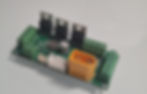
Integrated Charging System – Allows in-place charging via USB-C, DC barrel jack, or other connectors.
Battery Management System (BMS) – Includes cell balancing, undervoltage, and overvoltage protection.
Microcontroller (MCU) Interface – Enables advanced lighting control and system monitoring.
Remote Battery Monitoring – Tracks charge percentage and battery status in real time.
Optimized Power & Signal Routing – Ensures efficient power distribution and minimal interference.
Thermal Management – Designed for proper heat dissipation and reliable operation.
Manufacturing-Friendly Design – Ensures ease of assembly and long-term durability.
Defining The Requirements
Defining the requirements was a crucial first step in the design process. We focused on key aspects such as compatibility with RGB and programmable LED PCBs, battery management, and efficient power distribution. Additionally, we prioritized the need for a compact form factor, given the limited space available for the PCB. The requirements also included ensuring safe operation with the 3-cell LiPo battery, integrating charging capabilities, and providing a way to remotely monitor battery status. Once these core needs were clearly defined, we were able to proceed with designing the PCB to meet these specifications.


PCB Design
After defining the requirements, we designed the PCB with a compact, double-sided layout to optimize space and efficiency. We carefully routed power and signal traces to ensure reliable operation, proper heat dissipation, and minimal interference. The battery management system (BMS) and charging circuit were strategically placed for balanced power distribution and protection. Components were arranged to support efficient microcontroller communication and seamless integration with RGB and programmable LED PCBs. The final design prioritized both functionality and manufacturability, ensuring a robust and high-performance solution.
PCB Manufacturing
PCB manufacturing involved selecting high-quality materials and components, followed by precise fabrication to ensure the design specifications were met. The board was produced using advanced techniques such as double-sided PCB assembly and automated soldering processes to ensure reliable connections and efficient performance. Once the PCB was assembled, thorough testing was carried out, including electrical testing for proper voltage regulation, battery management, and microcontroller functionality. We also conducted functional testing to ensure the LED control system, charging circuit, and remote battery monitoring worked as intended. Any potential issues were identified and addressed during the testing phase to ensure a high-quality, reliable final product.
4o mini


Now, you've seen one our projects, but what about yours?
Get In Touch
today by clicking 'Get a Quote' at the top of the page.
bottom of page